

Measuring Atomic Steps
>>Sub-Nanometer Motion
Measuring Surface Roughness
Additional Information
PicoQ® Sensor Technology
MadPLL® Brochure
AFM Video Tutorial
Laser Focus World Article
Related Products
SPM-M Kit
Tuning Forks
MadPLL®
Nano-HS Series
Nano-LP Series
Questions?
E-Mail Us
Sub-Nanometer MotionMad City Labs nanopositioners have unmatched precision and resolution capabilities due to the inherent low-noise properties of proprietary PicoQ® sensor technology. A relevant application for nanopositioning is atomic force microscopy (AFM). Imaging calibrated samples using an AFM is a demanding application of nanopositioning systems. The following tests involve a Mad City Labs long range, low-profile nanopositioning system equipped with PicoQ® sensor technology (model Nano-LP100) performing a 1nm peak-to-peak sine wave and steps of 0.095 nm (95 pm), externally verified with a calibrated AFM. The results of these tests are significant; if a nanopositioner's inherent position noise is larger than 0.1 nm, it cannot move in externally-detectable 95 pm step intervals. The AFM measurements below are yet another confirmation that Mad City Labs nanopositioners with PicoQ® sensor technology set the standard for the lowest position noise on the market. Inherent position noise of nanopositioning systems with PicoQ® sensors has already been shown to be in the 10s of pm/√Hz [MacKay, James F. Understanding noise at the nanometer scale." Laser Focus World, 43.3, (2007)]. Please click on a heading to view a topic. Click the heading a second time to collapse the topic. |
Testing Principle
The AFM probe tip is positioned in proximity to the sample surface using the Z-axis of a nanopositioner. The distance between the probe tip and the sample surface is directly related to the magnitude of the force between the tip and sample. The nanopositioner is moved to maintain constant force between the tip and the surface. In a typical experiment, the tip is scanned along the X and Y axes. In this experiment, the Z-axis position is measured directly to provide a height measurement of the sample. Mad City Labs nanopositioners include integrated, direct measurement position sensors with PicoQ® sensor technology, already calibrated using NIST-traceable interferometric methods. Any displacement of the moving portion of the nanopositioner will yield a change in position sensor output, with the resolution ultimately limited by the noise of the nanopositioning system. Total AFM noise must be sufficiently low in order to externally measure sub-nanometer motion. Measuring the output of the nanopositioner's absolute position sensors assures accurate scan size and Z-axis position of the probe as it scans over the surface. |
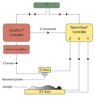
Test SetupIn the following tests, the AFM instrument consisted of a Nano-HS3 nanopositioning system with PicoQ® sensor technology for XYZ probe motion mounted on a SPM-MZ for Z axis coarse approach. A MadPLL® was used for closed loop feedback to maintain probe position in Z and an etched Tungsten tip attached to a quartz tuning fork was used as the imaging probe. Data were acquired using AFMView™ software, and analyzed and presented using SPIP® software.
|
1nm Sine-Wave Motion Performed by a 100 Micron Range Nanopositioner
A Silicon (111) substrate of single atomic layer steps was mounted to a Nano-LP100 with PicoQ® sensor technology, operating in closed loop, which was placed underneath the AFM described in the Test Setup section, above.
The Z-axis of the Nano-LP100 was commanded with a 1nm peak-to-peak sine wave at approximately 0.8 Hz using a 20 bit digital interface, causing the Silicon substrate to move in a 1nm peak-to-peak sine wave in the Z direction. No XY scanning was involved in this test while the sample nanopositioner (Nano-LP100) and the AFM maintained constant XY position. The sine-wave motion of the Nano-LP100 Z-axis carrying the Silicon substrate caused the MadPLL® to adjust the Z-axis position of the probe in order to maintain a constant force between the probe and Silicon substrate, and the probe's Z-axis position was measured and recorded. The test was performed over 600 iterations. The data result in a two dimensional colored image, with the X-axis representing time, Y-axis representing the iteration number, and the colors representing the displacement of the AFM probe [Figure 1].
The experimental question is: can the Nano-LP100 perform a 1 nm peak to peak motion? The data confirm that it can, as externally detected and measured by the AFM. Figure 2 shows a single test cycle of the 1 nm sine wave probe displacement measurements:
|
95 pm Steps Performed by a 100 Micron Range NanopositionerA Silicon (111) substrate of single atomic layer steps was mounted to a Nano-LP100, with PicoQ® sensors, operating in closed loop and placed underneath the AFM described in the Test Setup section, above. For a 100 micron range nanopositioning system with a 20 bit DAC, 95 pm represents a 1 bit change in the DAC output. The Z-axis of the Nano-LP100 was commanded in 95 pm square wave, i.e. in repeated 95 pm steps between two positions, at approximately 0.8 Hz. No XY scanning was involved in this test while the sample nanopositioner (Nano-LP100) and AFM maintained constant XY position. The stepping motion of the Nano-LP100 Z-axis carrying the Silicon substrate caused the MadPLL® to adjust the Z-axis position of the probe in order to maintain a constant force between the probe and Silicon substrate, and the probe's Z-axis position was measured and recorded. The test was performed over 600 iterations. The data result in a two dimensional colored image, with the X-axis representing time, Y-axis representing the iteration number, and the colors representing the Z axis displacement of the AFM probe [Figure 3].
The experimental question is: can the Nano-LP100 perform repeated 95 pm steps? The data confirms that it can, as externally detected and measured by the AFM. |
860 pm Steps Performed by a 450 Micron Range NanopositionerA Silicon (111) substrate of single atomic layer steps was mounted to a 450 micron range Z axis nanopositioner with PicoQ® sensors, operating in closed loop and placed underneath the AFM described in the Test Setup section, above. For a 450 micron range nanopositioning system with a 20 bit DAC, 860 pm represents a 2 bit change in the DAC output. The Z-axis nanopositioner was commanded in a 860 pm square wave, i.e. in repeated 860 pm steps between two positions. No XY scanning was involved in this test while the sample Z axis nanopositioner and AFM maintained constant XY position. The stepping motion of the Z-axis nanopositioner carrying the Silicon substrate caused the MadPLL® to adjust the Z-axis position of the probe in order to maintain a constant force between the probe and Silicon substrate, and the probe's Z-axis position was measured and recorded. The test was performed over 256 iterations. The data result in a two dimensional colored image, with the X-axis representing time, Y-axis representing the iteration number, and the colors representing the Z axis displacement of the AFM probe [Figure 4].
The experimental question is: can the 450 micron range Z axis nanopositioner perform repeated 860 pm steps? The data confirms that it can, as externally detected and measured by the AFM. |
Additional Information | ||
|
Laser Focus World Article  NANOPOSITIONING: Piezoelectric nanopositioners forge low-cost atomic force microscope |
AFM Video Tutorial |
MadPLL® Brochure |
Related Products |
Copyright © 2024